
Real Time Clock(DS1307) with AVR (Redirected from A6.AVR Interfacing: RTC DS1307)
Contents
[hide]Basics
The Real time clock DS1307 IC basically is stand alone time clock. Well, basically we can use a micrcontroller to keep time, but the value would go off as soon as it is powered off.
The RTC DS1307 is a handy solution to keep time all the way, when it is powered by a coin cell.
It is uses I²C (Inter-Integrated Circuit) protocol, referred to as I-squared-C, I-two-C, or IIC for communication with the micrcontroller.
Check the Basics of I2C here, if you are not familiar with it. For details of I2C in AVR, go through AVR Communication Protocols tutorial.
The first thing that the MCU sends to the slave (RTC) is the device ID. The device ID for DS1307, shown below. It also tells weather we want to write to or read from the RTC.
| 7 | 6 | 5 | 4 | 3 | 2 | 1 | 0 |
| 1 | 1 | 0 | 1 | 0 | 0 | 0 | R/W |
- bit-0 is 0 than we Write to RTC
- bit-0 is 1 we Read from RTC.
This is defined in the code as:
- #define C_Ds1307ReadMode_U8 0xD1u // DS1307 ID
- #define C_Ds1307WriteMode_U8 0xD0u // DS1307 ID
The RTC keeps the date and time arranged in it's memory as shown below:
| ADDRESS | FUNCTION | RANGE |
|---|---|---|
| 00h | Seconds | 00–59 |
| 01h | Minutes | 00–59 |
| 02h | Hours | 01-12/00-24 |
| 03h | Day | 01–07 |
| 04h | Date | 01–31 |
| 05h | Month | 01–12 |
| 06h | Year | 00–99 |
| 07h | Control | |
| 08h to 3Fh | RAM | 00h–FFh |
Write to the addresses above we can set the time, and once we set it, we can read it any time we need.
The address 0x07 is a control registered as described below:
| 7 | 6 | 5 | 4 | 3 | 2 | 1 | 0 |
| OUT | 0 | 0 | SQWE | 0 | 0 | RS1 | RS0 |
We write 0x00 to Control register to disable SQW-Out. We do not use any other bits from it, so you need not worry.
Initialize
Now we can initialize the RTC with the code below
- void RTC_Init(void)
- {
- I2C_Init(); // Initialize the I2c module.
- I2C_Start(); // Start I2C communication
- I2C_Write(C_Ds1307WriteMode_U8); // Connect to DS1307 by sending its ID on I2c Bus
- I2C_Write(C_Ds1307ControlRegAddress_U8);// Select the Ds1307 ControlRegister to configure Ds1307
- I2C_Write(0x00); // Write 0x00 to Control register to disable SQW-Out
- I2C_Stop(); // Stop I2C communication after initializing DS1307
- }
Set Date and Time
- void RTC_SetDateTime(rtc_t *rtc)
- {
- I2C_Start(); // Start I2C communication
- I2C_Write(C_Ds1307WriteMode_U8); // connect to DS1307 by sending its ID on I2c Bus
- I2C_Write(C_Ds1307SecondRegAddress_U8); // Request sec RAM address at 00H
- I2C_Write(rtc->sec); // Write sec from RAM address 00H
- I2C_Write(rtc->min); // Write min from RAM address 01H
- I2C_Write(rtc->hour); // Write hour from RAM address 02H
- I2C_Write(rtc->weekDay); // Write weekDay on RAM address 03H
- I2C_Write(rtc->date); // Write date on RAM address 04H
- I2C_Write(rtc->month); // Write month on RAM address 05H
- I2C_Write(rtc->year); // Write year on RAM address 06h
- I2C_Stop(); // Stop I2C communication after Setting the Date
- }
Note: The date and time read from Ds1307 will be of BCD format, like:
- 0x12,0x39,0x26 for 12hr,39min and 26sec.
- 0x15,0x08,0x47 for 15th day,8th month and 47th year
Get Date and Time
- void RTC_GetDateTime(rtc_t *rtc)
- {
- I2C_Start(); // Start I2C communication
- I2C_Write(C_Ds1307WriteMode_U8); // connect to DS1307 by sending its ID on I2c Bus
- I2C_Write(C_Ds1307SecondRegAddress_U8); // Request Sec RAM address at 00H
- I2C_Stop(); // Stop I2C communication after selecting Sec Register
- I2C_Start(); // Start I2C communication
- I2C_Write(C_Ds1307ReadMode_U8); // connect to DS1307(Read mode) by sending its ID
- rtc->sec = I2C_Read(1); // read second and return Positive ACK
- rtc->min = I2C_Read(1); // read minute and return Positive ACK
- rtc->hour= I2C_Read(1); // read hour and return Negative/No ACK
- rtc->weekDay = I2C_Read(1); // read weekDay and return Positive ACK
- rtc->date= I2C_Read(1); // read Date and return Positive ACK
- rtc->month=I2C_Read(1); // read Month and return Positive ACK
- rtc->year =I2C_Read(0); // read Year and return Negative/No ACK
- I2C_Stop(); // Stop I2C communication after reading the Date
- }
Both the above functions use a simple structure shown below for easy access
- typedef struct
- {
- uint8_t sec;
- uint8_t min;
- uint8_t hour;
- uint8_t weekDay;
- uint8_t date;
- uint8_t month;
- uint8_t year;
- }rtc_t;
Example
Now, let's put together the all that we have discussed in a simple example to read and show the time on character LCD.
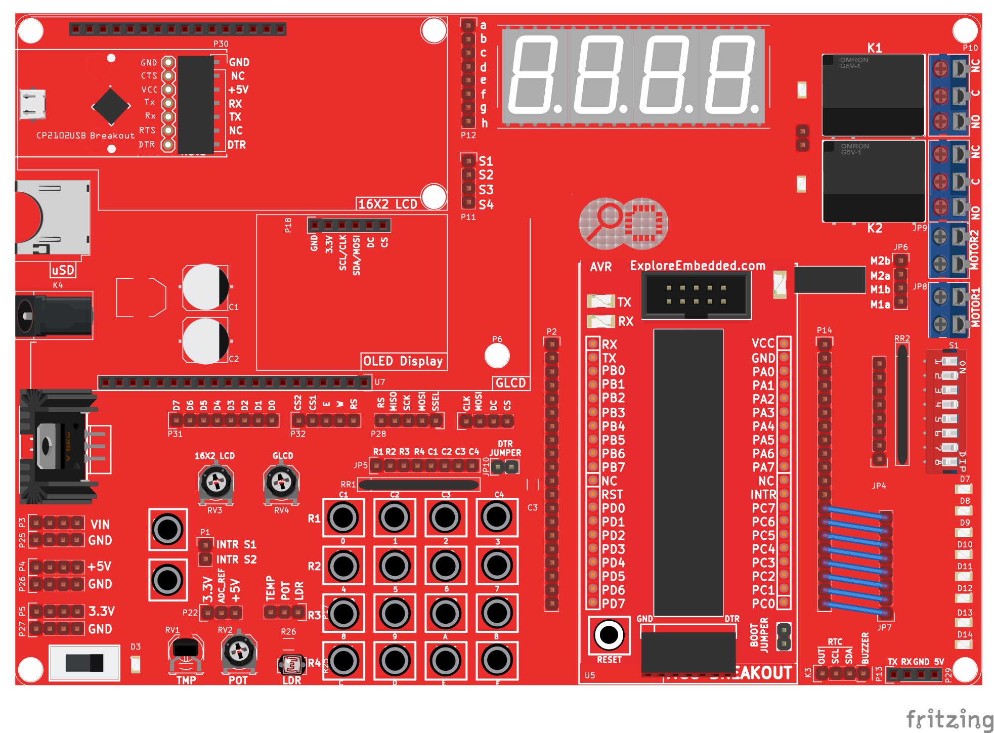
Hookup
_with_AVR_LCD_RTC.png)
_with_AVR_LCD_bb.png)
Code
| #include "rtc.h" | |
| #include "lcd.h" | |
| int main() | |
| { | |
| rtc_t rtc; | |
| /*Connect RS->PB0, RW->PB1, EN->PB2 and data bus to PORTB.4 to PORTB.7*/ | |
| LCD_SetUp(PB_0,PB_1,PB_2,P_NC,P_NC,P_NC,P_NC,PB_4,PB_5,PB_6,PB_7); | |
| LCD_Init(2,16); | |
| /*Connect SCL->PC0, SDA->PC1*/ | |
| RTC_Init(); | |
| rtc.hour = 0x10; // 10:40:20 am | |
| rtc.min = 0x40; | |
| rtc.sec = 0x00; | |
| rtc.date = 0x01; //1st Jan 2016 | |
| rtc.month = 0x01; | |
| rtc.year = 0x16; | |
| rtc.weekDay = 5; // Friday: 5th day of week considering monday as first day. | |
| /*##### Set the time and Date only once. Once the Time and Date is set, comment these lines | |
| and reflash the code. Else the time will be set every time the controller is reset*/ | |
| RTC_SetDateTime(&rtc); // 10:40:20 am, 1st Jan 2016 | |
| /* Display the Time and Date continuously */ | |
| while(1) | |
| { | |
| RTC_GetDateTime(&rtc); | |
| LCD_GoToLine(0); | |
| LCD_Printf("time:%2x:%2x:%2x \nDate:%2x/%2x/%2x",(uint16_t)rtc.hour,(uint16_t)rtc.min,(uint16_t)rtc.sec,(uint16_t)rtc.date,(uint16_t)rtc.month,(uint16_t)rtc.year); | |
| } | |
| return (0); | |
| } |
Schematic

_with_AVR.gif)
Video Tutorial
For those of you, who would like to watch instead of read we have made a video with all the gyan.
Downloads
Download the complete project folder from the below link:
https://github.com/ExploreEmbedded/ATmega32_ExploreUltraAvrDevKit/archive/master.zip
Have a opinion, suggestion , question or feedback about the article let it out here!
AVR I/O Register Configuration
In this tutorial we are going to discuss the port configuration of AVR/Atmel controllers or in general Atmega family. In this tutorial we will be using Atmega32 as reference, same will be applicable...

Basics of AVR 'C'
Let us look at the basics of 'C' for programming AVR Micrcontrollers in this tutorial. Simple stuff like setting and clearing bits is important to any project you do. It is often required to set...
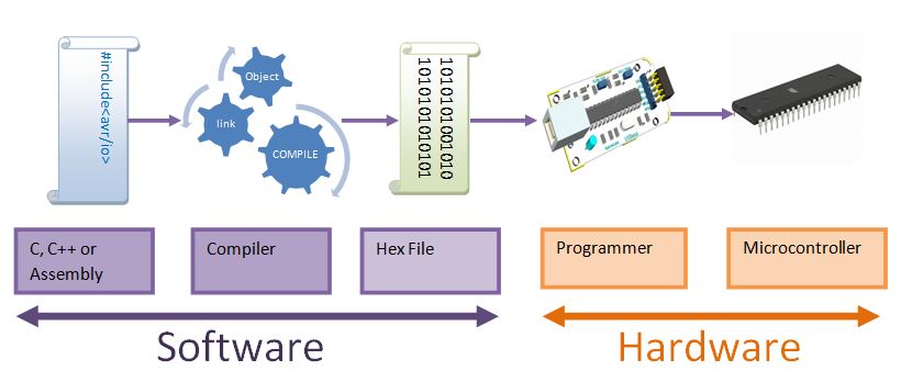
AVR Hardware and Software Setup
In this tutorial we will look at the basic setup required to get started with AVR series of microcontrollers. There are two aspects to it, the software and the hardware. Fortunately, we for AVR...
AVR Timer programming
Basics Timers come in handy when you want to set some time interval like your alarm. This can be very precise to a few microseconds. Timers/Counters are essential part of any modern...