
AVR External Interrupts
We have looked at the basics of AVR Interrupts, now let us go ahead and use the External Interrupts feature on the AVR MCUs.
Basics
When an interrupt occurs, the current program execution is stopped, the context is saved and the control jumps to Interrupt Service Routine (the ISR). When the ISR is executed, the main program execution is continued. This is usually the case with most simple Micro-controllers. We have been working with Atmega32 for this series, however there shouldn't be much difference making it work with other AVR MCUs. Now, let us look at how to configure the External Interrupts in AVR.
Steps to configure the Interrupts:
- Set INT1 and INT0 bits in the General Interrupt Control Register (GICR)
- Configure MCU Control Register (MCUCR) to select interrupt type.
- Set Global Interrupt(I-bit) Enable bit in the AVR Status Register(SREG)
- Handle the interrupt in the Interrupt Service Routine code.
INT1 and INT0 enable the two interrupts. MCUCR helps in configuring the type of interrupt, level, edge triggered etc. The I-bit in SREG is the master control for all interrupts in AVR micro-controller. Observe the sequence it is turned on after all the interrupts are configured. This prevents, any interrupt to occur before rest of them are configured.
General Interrupt Control Register (GICR)
The GICR Register shown below is used to enable INT0 and INT1 interrupts. These interrupts correspond to the two physical pins PD3 and PD4 respectively. The INT0 is configured to produce low level triggered and INT1 as falling edge triggered interrupt respectively. A counter is increment and displayed when the interrupt occurs.
| 7 | 6 | 5 | 4 | 3 | 2 | 1 | 0 |
|---|---|---|---|---|---|---|---|
| INT1 | INT0 | INT2 | - | - | - | IVSEL | IVCE |
MCU Control Register (MCUCR)
The MCUCR register allows us to configure the type of interrupt we need as shown by the table below:
| 7 | 6 | 5 | 4 | 3 | 2 | 1 | 0 |
|---|---|---|---|---|---|---|---|
| SE | SM2 | SM1 | SM0 | ISC11 | ISC10 | ISC01 | ISC00 |
| ISC01 | ISC00 | Description |
|---|---|---|
| 0 | 0 | The low level of INT0 generates an interrupt request. |
| 0 | 1 | Any logical change on INT0 generates an interrupt request. |
| 1 | 0 | The falling edge of INT0 generates an interrupt request. |
| 1 | 1 | The rising edge of INT0 generates an interrupt request. |
General Interrupt Flag Register(GIFR)
The bits of GIFR register are set when an interrupt occurs and cleared automatically when it is processed.
| 7 | 6 | 5 | 4 | 3 | 2 | 1 | 0 |
|---|---|---|---|---|---|---|---|
| INTF1 | INTF0 | INTF2 | - | - | - | - | - |
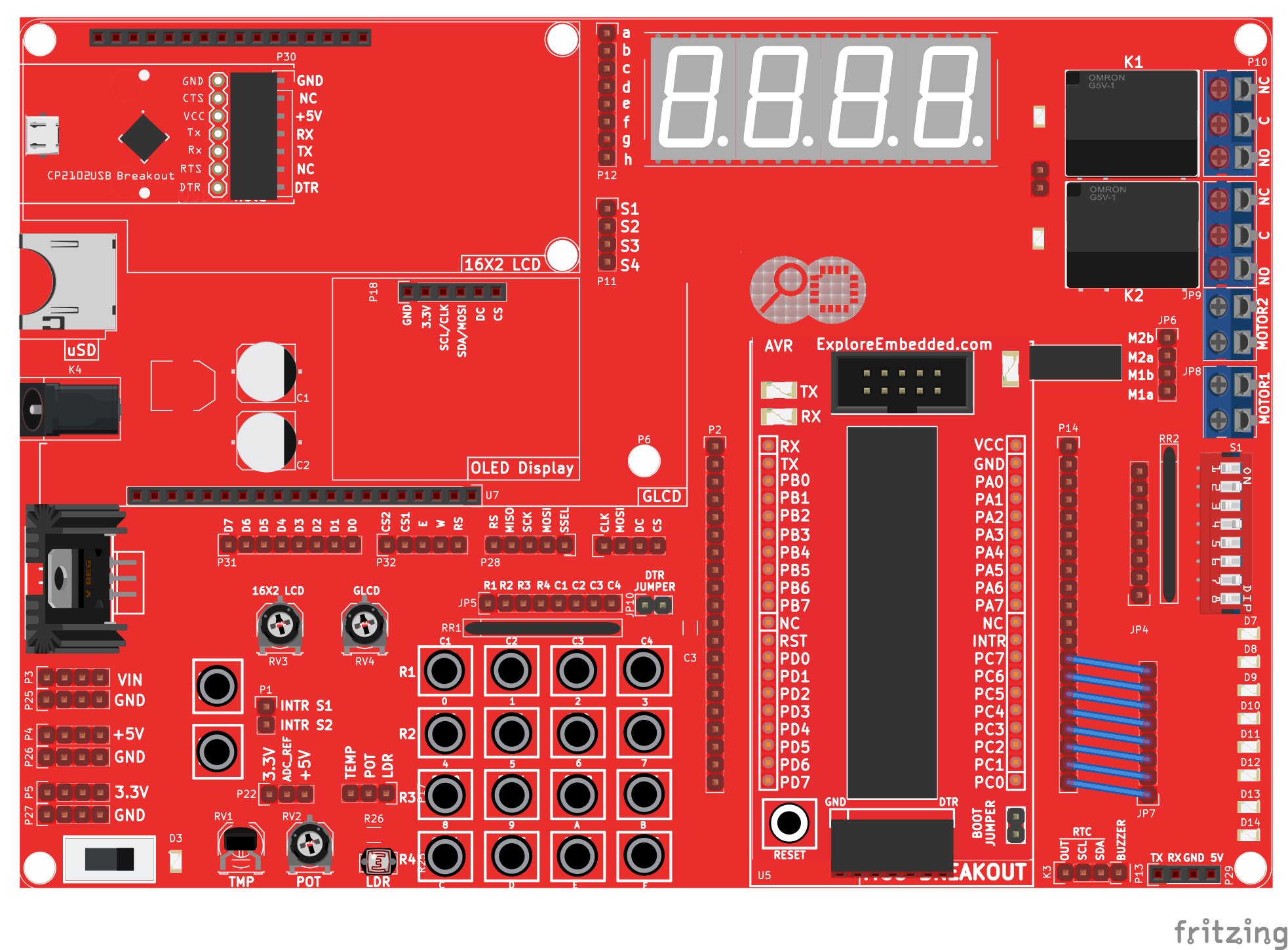
We will connect two switches to the two interrupt pins and show the status on a LCD. The connections are shown in the image below.
Hook Up
The Ultra AVR development board has two switches and also an inbuilt LCD. It is hooked up as shown below:

The Code
| #include<avr/io.h> | |
| #include<avr/interrupt.h> | |
| #include<util/delay.h> | |
| #include "lcd.h" | |
| volatile int cnt_zero,cnt_one; | |
| ISR (INT0_vect) //External interrupt_zero ISR | |
| { | |
| cnt_zero++; | |
| } | |
| ISR (INT1_vect) //External interrupt_one ISR | |
| { | |
| cnt_one++; | |
| } | |
| int main() | |
| { | |
| DDRC=0xff; //Configure PORTC(Lcd databus) as output | |
| DDRD=0xe0; //Configure INT0,INT1 as input and PORTD5-PORTD7(rs,rw,en) as output | |
| LCD_SetUp(PB_0,PB_1,PB_2,P_NC,P_NC,P_NC,P_NC,PB_4,PB_5,PB_6,PB_7); | |
| LCD_Init(2,16); | |
| GICR=0xc0; //Enable External Interrupts INT0 and INT1 | |
| MCUCR=0x08; //Configure INT0 active low level triggered and INT1 as falling edge | |
| sei(); // Enable global interrupts by setting global interrupt enable bit in SREG | |
| while(1) | |
| { | |
| LCD_Printf("EINT0:%4u\n",cnt_zero); | |
| LCD_Printf("EINT1:%4u\n",cnt_one); | |
| } | |
| } |
Let us look at the code in a little detail here.
- #include<avr/interrupt.h>
Line 2, includes the interrupt.h file, which includes all the interrupt definations.
- volatile int cnt_zero,cnt_one;
- ISR (INT0_vect) //External interrupt_zero ISR
- {
- cnt_zero++;
- }
The volatile keyword for cnt_zero and cnt_one variables ensures that these variables are not optimized by the compiler and also tells the compiler that these can change at anytime during the execution. Well, remember the switch can be pressed any time by the user, and volatile tells the compiler not to be over-smart and optimize it because it is no where used in the main code.
Now look at the ISR() function, it is template that is included with the avr-gcc compiler. All the interrupts that we saw in the basics tutorial can be configured as input to this function. The library take cares of saving the context, and switching back to main code when the ISR is complete. This is the cool thing about programming micro-controllers in C.
There are a few details which I have left out, like the names of the files which define the names of the interrupts and map them to the Interrupt vector Table (IVT). Should you have questions about any of these, comment below!
Video Tutorial
For those of you, who would like to watch instead of read we have made a video with all the gyan.
Downloads
Download the complete project folder from the below link:
https://github.com/ExploreEmbedded/ATmega32_ExploreUltraAvrDevKit/archive/master.zip
Demo Video
AVR I/O Register Configuration
In this tutorial we are going to discuss the port configuration of AVR/Atmel controllers or in general Atmega family. In this tutorial we will be using Atmega32 as reference, same will be applicable...

Basics of AVR 'C'
Let us look at the basics of 'C' for programming AVR Micrcontrollers in this tutorial. Simple stuff like setting and clearing bits is important to any project you do. It is often required to set...
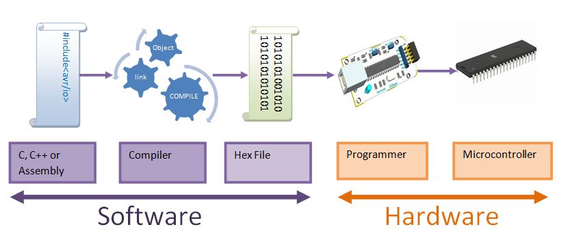
AVR Hardware and Software Setup
In this tutorial we will look at the basic setup required to get started with AVR series of microcontrollers. There are two aspects to it, the software and the hardware. Fortunately, we for AVR...

AVR Timer programming
Basics Timers come in handy when you want to set some time interval like your alarm. This can be very precise to a few microseconds. Timers/Counters are essential part of any modern...