
Interfacing Stepper Motor with Starter AVR Using A4988
In this tutorial we'll interface stepper motor with Starter AVR board using A4988 driver. For driving one stepper motor, one A4988 driver is required. A4988 has inbuilt translator so we can control this driver by just two pins, one for direction and one for controlling the steps.
Basic
A4988 comes with an output drive capacity of up to 35 V and ±2 A and compatible with 3.3V and 5V logic supply. A4988 is a 16 pin driver as shown in following figure. We'll look at all pins and it's functioning one by one.
 First two pins are Direction and Step which are actually used to control the movement of stepper motor. Direction pin will control the direction of motor, making this pin high will move motor in clockwise direction whereas making this pin low will move motor in anti-clockwise direction. For moving motor we have to simply give pulses to Step pin. Inputting one pulse on the STEP input drives the motor one microstep.
Third pin is SLEEP pin, which will be used to put driver in sleep mode whenever driver is not in use. Next pin is RESET pin. If we input logic low to this pin then all step signals will be ignored, so to enable the board this pin should be pulled high. As this pin is floating, if you don't want to control it with controller just connect it to SLEEP pin in order to enable the board as SLEEP pin is pulled high on board.
Next three pins are important as these three pins are used for micro stepping. Connect MS1, MS2 and MS3 as per following table to get particular step resolution. If you want to use motor in full step just keep them unconnected.

Next pin is Enable pin, which will turn on and off outputs. So make this pin low to enable output.
Next two pins VMOT and GND are for powering up the stepper motor. We can connect it to power supply from 8V to 35V, in our case we connected these pins to 12V supply. If you are using unregulated power supply then connect 47uF capacitor to protect driver against voltage spikes. After that next four pins are for connecting motor. 2A and 2B will be connected to one coil whereas 1A and 1B will be connected to another coil of stepper motor. Last two pins are for powering up the driver VDD and GND. We can connect it to either 3.3v or 5V, in our case we connected it to 5V supply.
After powering up the driver, the main thing to be done is setting the current limiting potetiometer on board as shown in figure, which will limit the current through the driver.

Rotating pot in clockwise direction will increase the current through the driver. We can do the current adjustment by adjusting the reference voltage VREF using potentiometer and using the following equation:
$$ Maximum Current = VREF / (8 * Rs)$$
Where, Rs = 0.1 for A4988
Now, measure VREF as shown in figure. In our case I adjusted it to 0.6V so Maximum Current becomes 0.75A. Now as per A4988 datasheet winding current could reach up to only 70% of Maximum Current in full step mode that is in our case, $$0.7 * 0.75 = 0.525A $$

Hookup
As shown in figure connect Enable to PD5, Direction to PD6 and Step to PD7. Give appropriate supply to VMOT and VDD and flash the given code. You will find that motor will rotate in 90 degrees and will complete one rotation in clockwise and will change the direction to complete one rotation in anti-clockwise.

Code
| #include <avr/io.h> | |
| #include "delay.h" | |
| #define stepPin PD7 //Define Step pin | |
| #define dirPin PD6 //Define Direction pin | |
| #define Enable PD5 //Define Enable pin | |
| int main(void) | |
| { | |
| int x,y; | |
| DDRD |= (1<<5)|(1<<6)|(1<<7); // Configure PORTD5, PORTD6, PORTD7 as output | |
| PORTD &= ~(1<<5); // Enable driver | |
| while (1) | |
| { | |
| PORTD |= (1<<6); //Make PORTD6 high to rotate motor in clockwise direction | |
| for(x=0; x<4; x++) //Give 50 pulses to rotate stepper motor by 90 degree's in full step mode | |
| { | |
| for(y=0; y<50; y++) | |
| { | |
| PORTD |=(1<<7); | |
| DELAY_us(700); | |
| PORTD &=~(1<<7); | |
| DELAY_us(700); | |
| } | |
| DELAY_ms(1000); | |
| } | |
| PORTD &= ~(1<<6); //Make PORTD6 high to rotate motor in anti-clockwise direction | |
| for(x=0; x<4; x++) //Give 50 pulses to rotate stepper motor by 90 degree's in full step mode | |
| { | |
| for(y=0; y<50; y++) | |
| { | |
| PORTD |=(1<<7); | |
| DELAY_us(700); | |
| PORTD &=~(1<<7); | |
| DELAY_us(700); | |
| } | |
| DELAY_ms(1000); | |
| } | |
| } | |
| } |
Demo
For full demo video visit our youtube channel https://www.youtube.com/watch?v=fYsiDZhr1ZU&feature=youtu.be
Downloads
Download the complete project folder from the below link:
https://github.com/ExploreEmbedded/ATmega32_ExploreStarterAvr/archive/master.zip
Have a opinion, suggestion , question or feedback about the article let it out here!
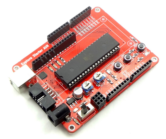
Setting Up Starter AVR
In this tutorial we will look at setting up the starter AVR board. Once you have done with this basic set up, you can use on board peripherals as well as many other peripherals which can be connected...
Blinky with Starter AVR
After setting up starter AVR board, we will start with simple LED blinking experiment. Two user LED's are provided on starter AVR board, we will use same for this experiment. Basic ...
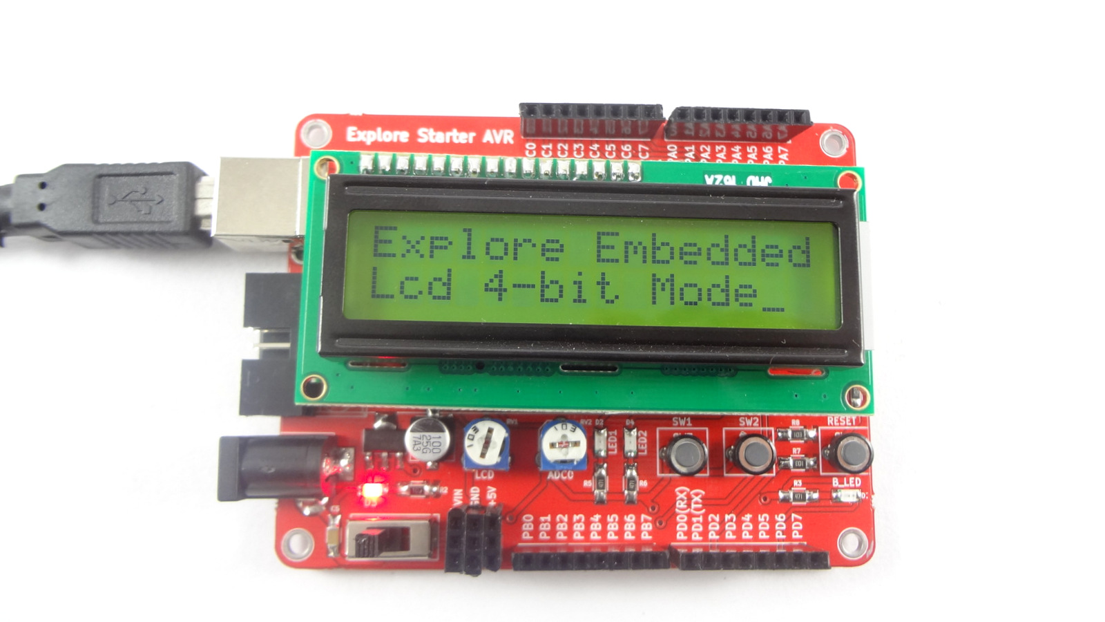
Interfacing LCD with Starter AVR
In this tutorial we'll look at how to interface different types of character LCD's to the starter AVR board. Basic Starter AVR board has female connector on board to connect LCD's...
Interfacing Seven Segment Display with Starter AVR
Now we will go further and will interface more complex peripherals. In this tutorial we will interface common anode 7 segment display to the starter AVR board. To get idea about basics of 7 segment...