
PIC18F4520 Timer
In this tutorial we are going to discuss the Timer module of PIC18F4520.
First we will see what are timers, their working and later we will configure the PIC18F4520 timers to generate delay of 100ms and 500ms respectively. At the end we will see how to use the ExploreEmdedded Timer library.
Contents
[hide]Timer Basics
As the name suggests these are used to measure the time or generate the accurate time delay. The microcontroller can also generate/measure the required time delays by running loops, but the timer/counter relieves the CPU from that redundant and repetitive task, allowing it to allocate maximum processing time for other tasks.
Timer is nothing but a simple binary counter that can be configured to count clock pulses(Internal/External). Once it reaches the Max value, it will roll back to zero setting up an OverFlow flag and generates the interrupt if enabled.

PIC Timer Module
PIC18F4520 has three indepenndent timer which can be used as timer,Counters or for PWM generation.
Below table provides the details of the three Timers.
| Timer | Size | Control Register | Count Register | Min Delay | Max Delay |
|---|---|---|---|---|---|
| TIMER0 | 8-bit | OPTION_REG | TMR0 | 0.2usec | 13.107ms |
| TIMER1 | 16-bit | T1CON | TMR1H,TMR1L | 0.2usec | 104.857ms |
| TIMER2 | 8-bit | T2CON | TMR2 | 0.2usec | 819usec |
Timer Calculation
PIC Oscillator frequency is divided by 4 and then fed to the controller, Now this this freq can be further divided by presacalar to generate the range of delays.
Time to increment the Timer count by one(timer tick) can be determined as below.
tick = (Prescalar/(Fosc/4)
tick = (Prescalar/(20Mhz/4))
$$tick = (Prescalar * 4)/Fosc$$
Now the Timer value for the required delay can be calculated as below.
Delay = TimerCount * tick
Count = (Delay/tick)
RegValue = TimerMax- Count
RegValue = TimerMax-(Delay/tick) = TimerMax - (Delay/((Prescalar *4)/Fosc))
$$RegValue = TimerMax-((Delay * Fosc)/(Prescalar*4))$$
Below table provides the formula for all the three Timers.
| Timer | Size | Formula for delay calculation |
|---|---|---|
| TIMER0 | 8-bit | $$RegValue = 256-((Delay * Fosc)/(Prescalar*4))$$ |
| TIMER1 | 16-bit | $$RegValue = 65536-((Delay * Fosc)/(Prescalar*4))$$ |
| TIMER2 | 8-bit | $$RegValue = 256-((Delay * Fosc)/(Prescalar*4))$$ |
Timer 0
The TMR0 module is an 8-bit timer/counter with the following features:
- 8-bit timer/counter
- Readable and writable
- 8-bit software programmable prescaler
- Internal or external clock select
- Interrupt on overflow from FFh to 00h
- Edge select for external clock
Timer0 Registers
The below table shows the registers associated with PIC18F4520 Timer0 module.
| Register | Description |
|---|---|
| OPTION_REG | This registers is used to configure the TIMER0 Prescalar, Clock Source etc |
| TMR0 | This register holds the timer count value which will be incremented depending on prescalar configuration |
| INTCON | This register contains the Timer0 overflow flag(TMR0IF) and corresponding Inetrrupt Enable flag(TMR0IE). |
| OPTION_REG | |||||||
| 7 | 6 | 5 | 4 | 3 | 2 | 1 | 0 |
| RBPU | INTEDG | T0CS | T0SE | PSA | PS2 | PS1 | PS0 |
RBPU: NA for Timers
INTEDG: NA for Timers
T0CS: TMR0 Clock Source Select bit
1-Transition on T0CKI pin
0-Internal instruction cycle clock (CLKO)
T0SE: TMR0 Source Edge Select bit
1-Increment on high-to-low transition on T0CKI pin
0-Increment on low-to-high transition on T0CKI pin
PSA: Prescaler Assignment bit
1-Prescaler is assigned to the WDT
0-Prescaler is assigned to the Timer0
PS2:PS0: Prescaler Rate Select bits

- Note:There is only one prescaler available which is mutually exclusively shared between the Timer0 module and the Watchdog Timer. A prescaler assignment for the Timer0 module means that there is no prescaler for the Watchdog Timer and vice versa. This prescaler is not accessible but can be configured using PS2:PS0 bits of OPTION_REG.
| INTCON | |||||||
| 7 | 6 | 5 | 4 | 3 | 2 | 1 | 0 |
| GIE | PIE | TMR0IE | INTE | RBIE | TMR0IF | INTF | RBIF |
GIE: Global Interrupt Enable bit
1-Enables all unmasked interrupts
0-Disables all interrupts
PIE: Peripheral Interrupt Enable bit
1-Enables all unmasked peripheral interrupts
0-Disables all peripheral interrupts
TMR0IE: TMR0 Overflow Interrupt Enable bit
1-Enables the TMR0 interrupt
0-Disables the TMR0 interrupt
INTE: NA for Timers
RBIE: NA for Timers
TMR0IF: TMR0 Overflow Interrupt Flag bit
1-TMR0 register has overflowed (must be cleared in software)
0-TMR0 register did not overflow
INTF: NA for Timers
RBIF: NA for Timers

Delay Calculations for 1ms @20Mhz with Prescalar as 32: $$RegValue = 256-(Delay * Fosc)/(Prescalar*4)) = 256-((1ms * 20Mhz)/(32*4)) = 256-156=100$$
Code
Below are the steps for configuring and using the Timer0 for delay generation:
- Calculate the Timer Count for the required delay.
- Set the Presaclar bits in OPTION_REG as per the delay calculations.
- Clear the PSAbit for using the prescalar.
- Select the Clock Source Internal/External using TOCS bit.
- Load the timer value into TMRO register.
- Enable the Timer0 Interrupt by setting TMR0IE bit
- Enable the Global and Peripheral interrupts by setting GIE and PIE bits
Below is the sample code to blink the LEDs with 1ms delay.
| #include<pic16f877a.h> | |
| char value = 0; | |
| #define SBIT_PS2 2 | |
| void interrupt timer_isr() | |
| { | |
| if(TMR0IF==1) | |
| { | |
| value=~value; // complement the value for blinking the LEDs | |
| TMR0 = 101; /*Load the timer Value, (Note: Timervalue is 101 instaed of 100 as the | |
| TImer0 needs two instruction Cycles to start incrementing TMR0 */ | |
| TMR0IF=0; // Clear timer interrupt flag | |
| } | |
| } | |
| void main() | |
| { | |
| TRISD=0x00; //COnfigure PORTD as output to blink the LEDs | |
| OPTION_REG = (1<<SBIT_PS2); // Timer0 with external freq and 32 as prescalar | |
| TMR0=100; // Load the time value for 1ms delay | |
| TMR0IE=1; //Enable timer interrupt bit in PIE1 register | |
| GIE=1; //Enable Global Interrupt | |
| PEIE=1; //Enable the Peripheral Interrupt | |
| while(1) | |
| { | |
| PORTD = value; | |
| } | |
| } |

Timer 1
The timer TMR1 module is an 16-bit timer/counter with the following features:
- 16-bit timer/counter with two 8-Bit register TMR1H/TMR1L
- Readable and writable
- software programmable prescaler upto 1:8
- Internal or external clock select
- Interrupt on overflow from FFFFh to 00h
- Edge select for external clock
Timer1 Registers
The below table shows the registers associated with PIC18F4520 Timer1 module.
| Register | Description |
|---|---|
| T1CON: | This registers is used to configure the TIMER1 Prescalar, Clock Source etc |
| TMRIH | This register holds the higher 8-bits of timer value. TMR1H and TMR1L are used in pair to increment from 0000 - FFFFh |
| TMRIL | This register holds the lower 8-bits of timer value. TMR1H and TMR1L are used in pair to increment from 0000 - FFFFh |
| PIR1 | This register contains the Timer1 overflow flag(TMR1IF). |
| PIE1 | This register contains the Timer1 Interrupt Enable flag(TMR1IE). |
| T1CON | |||||||
| 7 | 6 | 5 | 4 | 3 | 2 | 1 | 0 |
| — | — | T1CKPS1 | T1CKPS0 | T1OSCEN | T1SYNC | TMR1CS | TMR1ON |
T1CKPS1:T1CKPS0:Timer1 Input Clock Prescale Select bits
11 = 1:8 prescale value
10 = 1:4 prescale value
01 = 1:2 prescale value
00 = 1:1 prescale value
T1OSCEN: Timer1 Oscillator Enable Control bit
1-Oscillator is enabled
0-Oscillator is shut-off
T1SYNC: Timer1 External Clock Input Synchronization Control bit
1-Do not synchronize external clock input
0-Synchronize external clock input
TMR1CS: Timer1 Clock Source Select bit
1-External clock from pin RC0/T1OSO/T1CKI (on the rising edge)
0-Internal clock (FOSC/4)
TMR1ON: Timer1 On bit
1-Enables Timer1
0-Stops Timer1

Delay Calculations for 100ms @20Mhz with Prescalar as 8: $$RegValue = 65536-(Delay * Fosc)/(Prescalar*4)) = 65536-((100ms * 20Mhz)/(8*4)) = 3036 = 0xBDC$$
Code
Below are the steps for configuring and using the Timer1 for delay generation:
- Calculate the Timer Count for the required delay.
- Set the Presaclar bits in T1CON as per the delay calculations.
- Select the Clock Source Internal/External using TMR1CS bit.
- Load the timer value into TMR1H,TMR1L register.
- Enable the Timer1 Interrupt by setting TMRIE bit
- Enable the Global and Peripheral interrupts by setting GIE and PIE bits
- Finally start the timer by setting TMR1ON bit
Below is the sample code to blink the LEDs with 1ms delay.
| #include<pic16f877a.h> | |
| char value = 0; | |
| #define SBIT_PS1 5 | |
| #define SBIT_PS0 4 | |
| void interrupt timer_isr() | |
| { | |
| if(TMR1IF==1) | |
| { | |
| value=~value; // complement the value for blinking the LEDs | |
| TMR1H=0x0B; // Load the time value(0xBDC) for 100ms delay | |
| TMR1L=0xDC; | |
| TMR1IF=0; // Clear timer interrupt flag | |
| } | |
| } | |
| void main() | |
| { | |
| TRISD=0x00; //COnfigure PORTD as output to blink the LEDs | |
| T1CON = (1<<SBIT_PS1) | (1<<SBIT_PS0); // Timer0 with external freq and 8 as prescalar | |
| TMR1H=0x0B; // Load the time value(0xBDC) for 100ms delay | |
| TMR1L=0xDC; | |
| TMR1IE=1; //Enable timer interrupt bit in PIE1 register | |
| GIE=1; //Enable Global Interrupt | |
| PEIE=1; //Enable the Peripheral Interrupt | |
| TMR1ON = 1; //Start Timer1 | |
| while(1) | |
| { | |
| PORTD = value; | |
| } | |
| } |

Timer 2
The TImer2 module is an 8-bit timer/counter with the following features:
- 8-bit timer/counter
- Readable and writable
- Software programmable prescaler/PostScaler upto 1:16
- Interrupt on overflow from FFh to 00h
Timer2 Registers
The below table shows the registers associated with PIC16f877A Timer0 module.
| Register | Description |
|---|---|
| T2CON | This registers is used to configure the TIMER2 Prescalar, Clock Source etc |
| TMR2 | This register holds the timer count value which will be incremented depending on prescalar configuration |
| PIR1 | This register contains the Timer2 overflow flag(TMR2IF). |
| PIE1 | This register contains the Timer2 Interrupt Enable flag(TMR2IE). |
| T2CON | |||||||
| 7 | 6 | 5 | 4 | 3 | 2 | 1 | 0 |
| — | TOUTPS3 | TOUTPS2 | TOUTPS1 | TOUTPS0 | TMR2ON | T2CKPS1 | T2CKPS0 |
TOUTPS3:TOUTPS0: Timer2 Output Postscale Select bits
0000 = 1:1 postscale
0001 = 1:2 postscale
0010 = 1:3 postscale
•
•
•
1111 = 1:16 postscale
TMR2ON: Timer2 On bit
1-Timer2 is on
0-Timer2 is off
T2CKPS1:T2CKPS0: Timer2 Clock Prescale Select bits
00 = Prescaler is 1
01 = Prescaler is 4
1x = Prescaler is 16

Generating 1sec delay using Timer2:
As the timer2 is 8-bit and supports 1:16 prescalar, it is not possible to directly generate the delay of 1sec. The max delay with 1:16 prescaler will be:
$$Delay = 256 * (Prescaler*4)/Fosc = 256 * 16*4/20Mhz=819us$$
Now 500us can be generated using timers which will be used to increment a counter 2000 times to get 1sec delay.
Delay Calculations for 500usec @20Mhz with Prescalar as 16:
$$RegValue = 256-(Delay * Fosc)/(Prescalar*4)) = 256-((500us* 20Mhz)/(16*4)) = 256-156=100$$
Code
Below are the steps for configuring and using the Timer2 for delay generation:
- Calculate the Timer Count for the required delay.
- Set the Prescaler bits in T2CON as per the delay calculations.
- Load the timer value into TMR2 register.
- Enable the Timer2 Interrupt by setting TMR2IE bit
- Enable the Global and Peripheral interrupts by setting GIE and PIE bits
- Finally start the Timer2 by setting TMR2ON bit
Below is the sample code to blink the LEDs with 1sec delay.
| #include<pic16f877a.h> | |
| #define SBIT_T2CKPS1 1 | |
| char value = 0; | |
| int count = 0; | |
| void interrupt timer_isr() | |
| { | |
| if(TMR2IF==1) | |
| { | |
| TMR2 = 101; /*Load the timer Value, (Note: Timervalue is 101 instead of 100 as the | |
| Timer2 needs two instruction Cycles to start incrementing TMR2 */ | |
| TMR2IF=0; // Clear timer interrupt flag | |
| if(count>=2000) //500us * 2000=1000000us=1sec | |
| { | |
| count=0; | |
| value=~value; // complement the value for blinking the LEDs | |
| } | |
| else | |
| { | |
| count++; // Keep incrementing the count till it reaches 2000 to generate 1sec delay | |
| } | |
| } | |
| } | |
| void main() | |
| { | |
| TRISD=0x00; //COnfigure PORTD as output to blink the LEDs | |
| T2CON = (1<<SBIT_T2CKPS1); // Timer2 with external freq and 16 as prescalar | |
| TMR2=100; // Load the timer value for 500us delay | |
| TMR2IE=1; //Enable timer interrupt bit in PIE1 register | |
| GIE=1; //Enable Global Interrupt | |
| PEIE=1; //Enable the Peripheral Interrupt | |
| TMR2ON = 1; | |
| while(1) | |
| { | |
| PORTD = value; | |
| } | |
| } |


Downloads
Download the complete project folder from the below link:
Hardware design Files and Code Library
Have a opinion, suggestion , question or feedback about the article let it out here!

Pic18f4520 Starter Board Introduction
Kit Contents: PIC18F4520 Starter Board comes with the following features: PIC18F4520 MCU with ds30 bootloader LCD 16x2 breakout. On Board Usb-To-Serial...

Pic18f4520 MPLABx Setup
In this tutorial we will see how to setup a Mplabx project to generate .hex file for Pic18f4520 MPLABx Setup Steps Step1: Open the MPLABx software and select the...
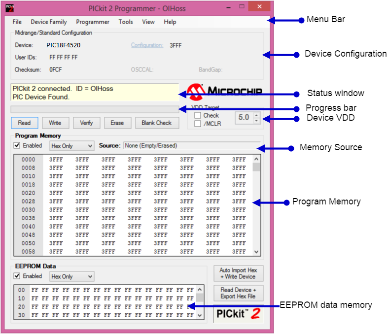
Uploading Hex File To PIC18F4520 Using Pickit2
In this tutorial we will see how to upload hex file using the below PICKit 2 programmer. Installing Pickit 2 Software Download and Install the Pickit2 software from...
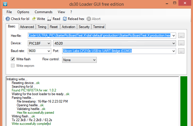
Uploading Hex File to PIC18F4520 Using Ds30 Bootloader
We will see in this tutorial how to upload hex file to PIC controller using DS30 loader GUI. Installing DS30 Software Download the DS30 Loader Software from the...