RTC Using Explore M3
In this tutorial we will see how to generate the PWM signals on Explore M3.
Prerequisites
Please check this tutorial for detailed explanation on inbuilt Lpc1768 RTC module.
If you are doing it for the first time, then check the below links to setup the project for generating the .bin file.
Code
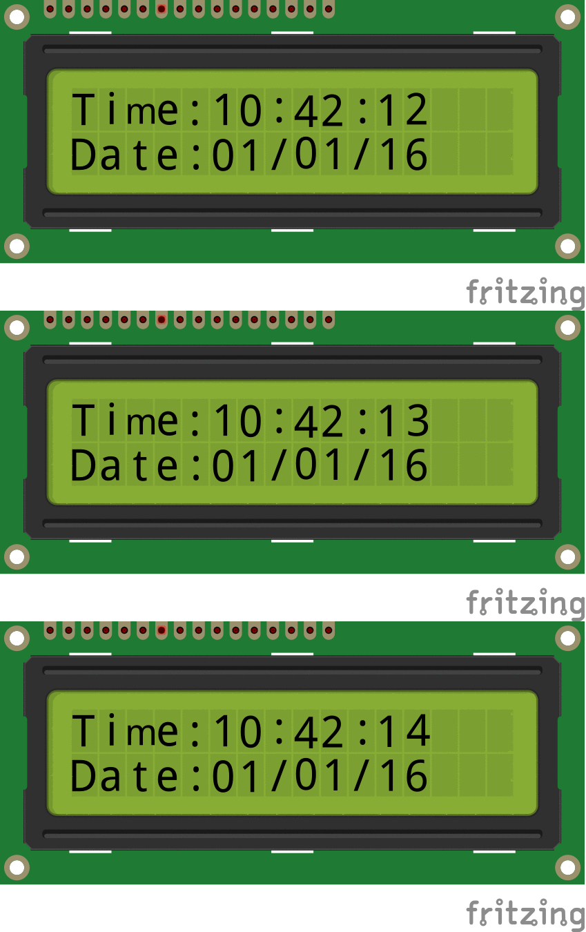
Below is the example code for RTC using Explore M3.
This file contains hidden or bidirectional Unicode text that may be interpreted or compiled differently than what appears below. To review, open the file in an editor that reveals hidden Unicode characters.
Learn more about bidirectional Unicode characters
| #include "rtc.h" | |
| #include "lcd.h" | |
| int main() | |
| { | |
| rtc_t rtc; | |
| SystemInit(); | |
| /* RS RW EN D0 D1 D2 D3 D4 D5 D6 D7*/ | |
| LCD_SetUp(5, 6, 7, P_NC, P_NC, P_NC, P_NC, 12, 13, 14, 15); | |
| LCD_Init(2,16); | |
| RTC_Init(); | |
| rtc.hour = 10; // 10:40:20 am | |
| rtc.min = 40; | |
| rtc.sec = 0; | |
| rtc.date = 1; //1st Jan 2016 | |
| rtc.month = 1; | |
| rtc.year = 16; | |
| rtc.weekDay = 5; // Friday: 5th day of week considering monday as first day. | |
| /*##### Set the time and Date only once. Once the Time and Date is set, comment these lines | |
| and reflash the code. Else the time will be set every time the controller is reset*/ | |
| RTC_SetDateTime(&rtc); // 10:40:20 am, 1st Jan 2016 | |
| /* Display the Time and Date continuously */ | |
| while(1) | |
| { | |
| RTC_GetDateTime(&rtc); | |
| LCD_GoToLine(0); | |
| LCD_Printf("time:%2d:%2d:%2d \nDate:%2d/%2d/%2d",(uint16_t)rtc.hour,(uint16_t)rtc.min,(uint16_t)rtc.sec,(uint16_t)rtc.date,(uint16_t)rtc.month,(uint16_t)rtc.year); | |
| } | |
| } |

