
Using Explore Cortex M3 (LPC1768) with mbed
A quick tutorial on using the Explore Cortex M3 (LPC1768) with mbed. Right now, the USB bootloader(mass storage) option does not work with mbed. However if you have a USB to Serial converter, you can definitely program it. This tutorial also applies for other bare metal LPC1768 boards.
Why USB boot-loader does not work?
The mbed online compiler does not allow specifing offest addresses for RAM and ROM which are required in order to make the boot-loader work. If you've figured out a way let us know.
Connecting the Hardware
You need a USB to Serial(UART) convertor in order to get this working. The neat thing about the NXP controllers is, they come with a UART boot-loader form the factory. Even though we put a USB boot-loader on top it, the serial boot-loader is still there for you.
We use the additional DTR and RTS signals to RESET and BOOT-LOAD the board respectively. If your converter does not have these lines, "hold down the ISP switch, RESET the board(press and release reset switch) and then release the ISP switch ". Do this action when programming the board from flash magic which I will describe below.

Converting mbed bin file to hex
We need a hex file in order to flash it using Flash magic. Use this bin2hex utility to convert the file to hex. Copy the bin2hex.exe to some folder, copy the bin file from mbed to the same folder. Enter the command below:
BIN2HEX <input_binary_filename> <output_hex_filename>
e.g bin2hex.exe led.bin led.hex
Transfer the file with the settings below and you've be done.

I did the test with a 16x2, character display, with the following code
- // Hello World! for the TextLCD
- #include "mbed.h"
- #include "TextLCD.h"
- TextLCD lcd(P1_25, P1_26, P1_27, P1_28, P1_29, P1_30); // rs, e, d4-d7
- int main() {
- lcd.printf("Explore LPC1768\n on mbed");
- }
and the results. . .

It would really be nice if we were able to define offset with the mbed compiler. We will work on it and see if there is anything else we can do about it.
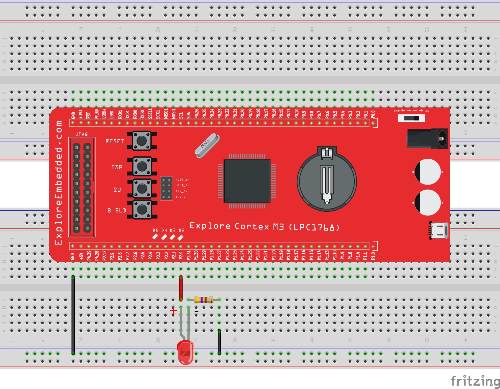
LPC1768: Led Blinking
This is first example on LPC1768 where we start with blinking the LEDs. In this tutorial, we are going to discuss how to configure the LPC1768 ports as GPIO and then send a low/high signal...
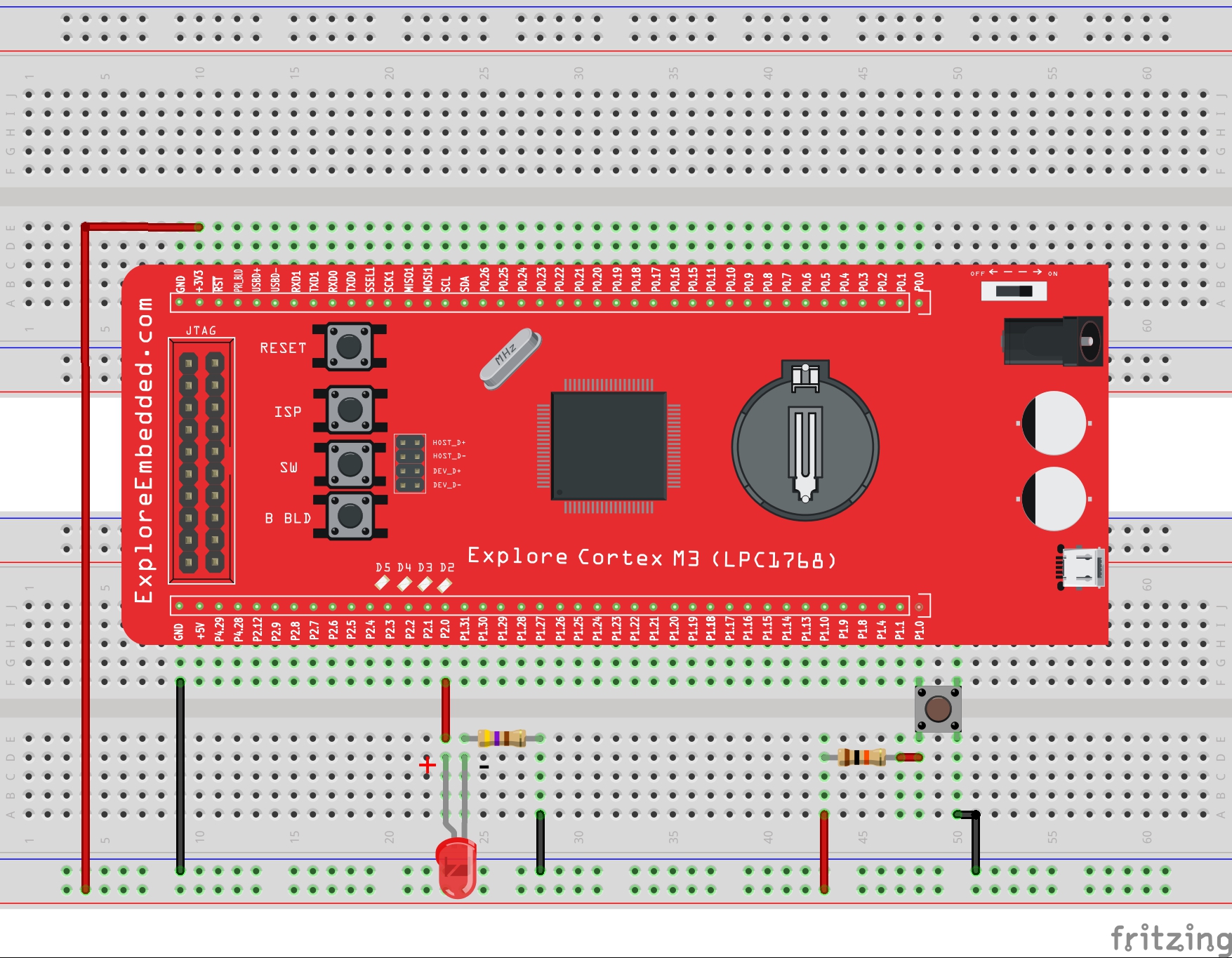
LPC1768: Switch and LED
This is second tutorial on LPC1768 where we are going to read the switches and turn ON/OFF the LEDs accordingly. LPC1768 has its GPIOs divided into five ports PORT0 - PORT4, although many of them...
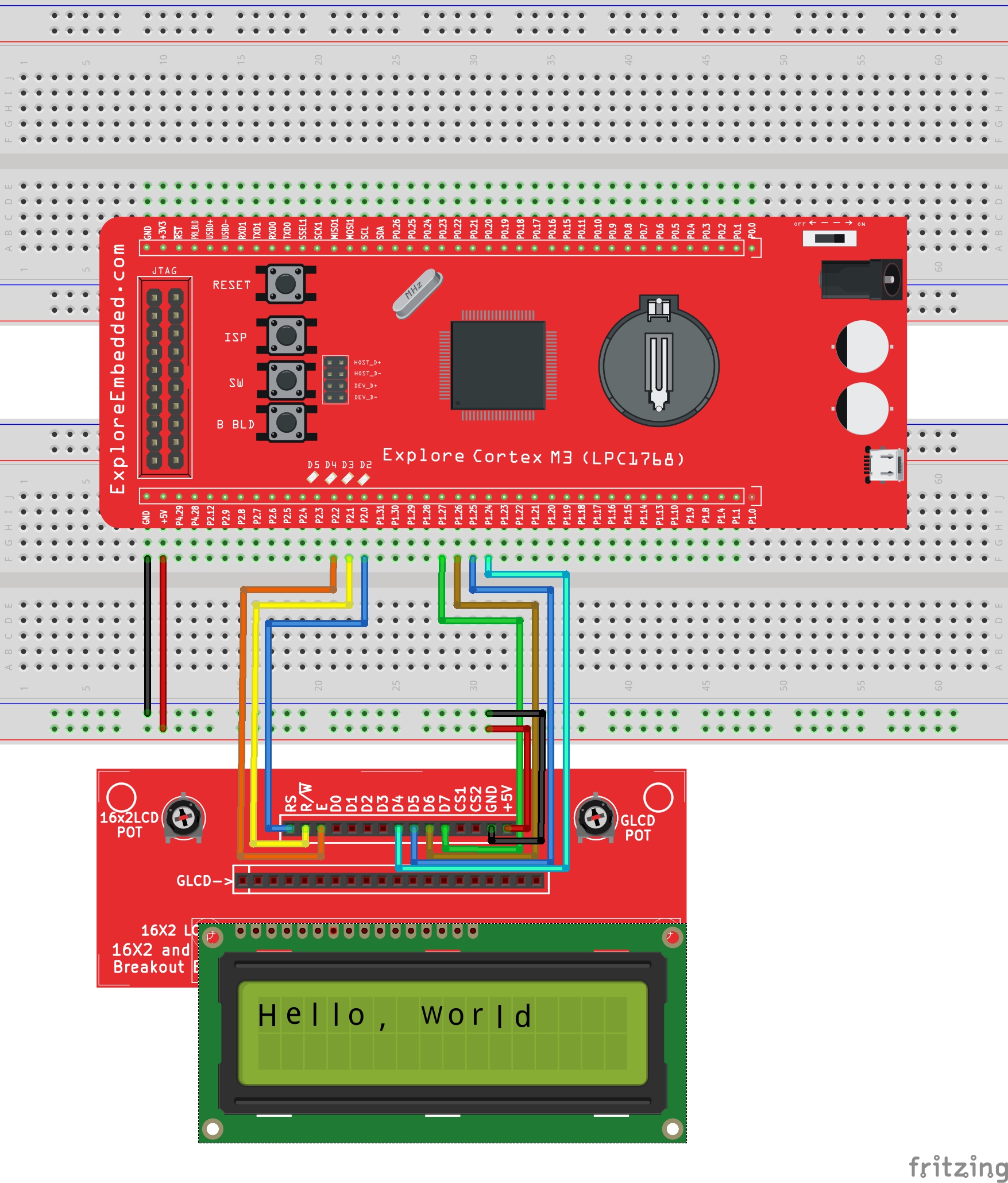
LPC1768: Lcd 4bit
In this tutorial we are going to see how to interface a 2x16 LCD with LPC1768 in 4-bit mode. As per the name the 2x16 has 2 lines with 16 chars on each lines. It supports all the ascii chars and is...

LPC1768: Lcd 8bit
In this tutorial we are going to see how to interface a 2x16 LCD with LPC1768 in 8-bit mode. As per the name the 2x16 has 2 lines with 16 chars on each lines. It supports all the ascii chars and is...