
Difference between revisions of "LPC1768: Switch and LED"
| Line 18: | Line 18: | ||
<b>PINSEL:</b> GPIO Pins Select Register<br> | <b>PINSEL:</b> GPIO Pins Select Register<br> | ||
| − | Almost all the LPC1768 pins are multiplexed to support more than 1 function. Every GPIO pin has a minimum of one function and max of four functions. The required function can be selected by configuring the PINSEL register. As there can be up to 4 functions associated with a GPIO pin, two bits for each pin are available to select the function. This | + | Almost all the LPC1768 pins are multiplexed to support more than 1 function. Every GPIO pin has a minimum of one function and max of four functions. The required function can be selected by configuring the PINSEL register. As there can be up to 4 functions associated with a GPIO pin, two bits for each pin are available to select the function. This implies that we need two PINSEL registers to configure a PORT pins. |
By this the first 16(P0.0-P0.16) pin functions of PORT0 can be selected by 32 bits of PINSELO register. The remaining 16 bits(P0.16-P0.32) are configured using 32bits of PINSEL1 register. | By this the first 16(P0.0-P0.16) pin functions of PORT0 can be selected by 32 bits of PINSELO register. The remaining 16 bits(P0.16-P0.32) are configured using 32bits of PINSEL1 register. | ||
As mentioned earlier every pin has max of four functions. Below table shows how to select the function for a particular pin using two bits of the PINSEL register. | As mentioned earlier every pin has max of four functions. Below table shows how to select the function for a particular pin using two bits of the PINSEL register. | ||
| − | {| class=" | + | {| class="table table-striped table-hover table-condensed table-bordered" |
| − | + | |-class="info" | |
| + | |Value|| Function || Enumeration | ||
|- | |- | ||
|00|| Primary (default) function, typically GPIO port || PINSEL_FUNC_0 | |00|| Primary (default) function, typically GPIO port || PINSEL_FUNC_0 | ||
| Line 36: | Line 37: | ||
<b>FIODIR:</b>Fast GPIO Direction Control Register.<br>This register individually controls the direction of each port pin. | <b>FIODIR:</b>Fast GPIO Direction Control Register.<br>This register individually controls the direction of each port pin. | ||
| − | {| class=" | + | {| class="table table-striped table-hover table-condensed table-bordered" |
| − | + | |-class="info" | |
| + | |Values|| Direction | ||
|- | |- | ||
|0|| Input | |0|| Input | ||
| Line 47: | Line 49: | ||
<b>FIOSET:</b>Fast Port Output Set Register.<br>This register controls the state of output pins. Writing 1s produces highs at the corresponding port pins. Writing 0s has no effect. Reading this register returns the current contents of the port output register not the physical port value. | <b>FIOSET:</b>Fast Port Output Set Register.<br>This register controls the state of output pins. Writing 1s produces highs at the corresponding port pins. Writing 0s has no effect. Reading this register returns the current contents of the port output register not the physical port value. | ||
| − | {| class=" | + | {| class="table table-striped table-hover table-condensed table-bordered" |
| − | + | |-class="info" | |
| + | |Values|| FIOSET | ||
|- | |- | ||
|0|| No Effect | |0|| No Effect | ||
| Line 58: | Line 61: | ||
<b>FIOCLR:</b>Fast Port Output Clear Register.<br>This register controls the state of output pins. Writing 1s produces lows at the corresponding port pins. Writing 0s has no effect. | <b>FIOCLR:</b>Fast Port Output Clear Register.<br>This register controls the state of output pins. Writing 1s produces lows at the corresponding port pins. Writing 0s has no effect. | ||
| − | {| class=" | + | {| class="table table-striped table-hover table-condensed table-bordered" |
| − | + | |-class="info" | |
| + | |Values|| FIOCLR | ||
|- | |- | ||
|0|| No Effect | |0|| No Effect | ||
| Line 73: | Line 77: | ||
<b>Input:</b> The current state of digital port pins can be read from this register, regardless of pin direction or alternate function selection (as long as pins are not configured as an input to ADC).<br> | <b>Input:</b> The current state of digital port pins can be read from this register, regardless of pin direction or alternate function selection (as long as pins are not configured as an input to ADC).<br> | ||
<b>Note:</b>It is recommended to configure the PORT direction and pin function before using it. | <b>Note:</b>It is recommended to configure the PORT direction and pin function before using it. | ||
| + | <br><br><br><br> | ||
=Hardware Connections= | =Hardware Connections= | ||
Revision as of 19:26, 14 April 2016
Contents
[hide]Objective
This is second tutorial on LPC1768 where we are going to read the switchs and turn ON/OFF the LEDs accordingly.
Register Configuration
As all the LPC1768 SFRs(Special Function Registers) are defined in lpc17xx.h, this has to be included at the beginning of our project/code.
LPC1768 has its GPIOs divided into five ports PORT0 - PORT4, although many of them are not physically 32bit wide. Refer the data sheet for more info.
Register Configuration
The Below registers will be used for Configuring and using the GPIOs registers for sending and receiving the Digital signals. A structure LPC_GPIOn(n= 0,1,2,3) contains all the registers for required for GPIO operation. Refer lpc17xx.h file for more info on the registers.
PINSEL: GPIO Pins Select Register
Almost all the LPC1768 pins are multiplexed to support more than 1 function. Every GPIO pin has a minimum of one function and max of four functions. The required function can be selected by configuring the PINSEL register. As there can be up to 4 functions associated with a GPIO pin, two bits for each pin are available to select the function. This implies that we need two PINSEL registers to configure a PORT pins.
By this the first 16(P0.0-P0.16) pin functions of PORT0 can be selected by 32 bits of PINSELO register. The remaining 16 bits(P0.16-P0.32) are configured using 32bits of PINSEL1 register.
As mentioned earlier every pin has max of four functions. Below table shows how to select the function for a particular pin using two bits of the PINSEL register.
| Value | Function | Enumeration |
| 00 | Primary (default) function, typically GPIO port | PINSEL_FUNC_0 |
| 01 | First alternate function | PINSEL_FUNC_1 |
| 10 | Second alternate function | PINSEL_FUNC_2 |
| 11 | Third alternate function | PINSEL_FUNC_3 |
FIODIR:Fast GPIO Direction Control Register.
This register individually controls the direction of each port pin.
| Values | Direction |
| 0 | Input |
| 1 | Output |
FIOSET:Fast Port Output Set Register.
This register controls the state of output pins. Writing 1s produces highs at the corresponding port pins. Writing 0s has no effect. Reading this register returns the current contents of the port output register not the physical port value.
| Values | FIOSET |
| 0 | No Effect |
| 1 | Sets High on Pin |
FIOCLR:Fast Port Output Clear Register.
This register controls the state of output pins. Writing 1s produces lows at the corresponding port pins. Writing 0s has no effect.
| Values | FIOCLR |
| 0 | No Effect |
| 1 | Sets Low on Pin |
FIOPIN:Fast Port Pin Value Register.
This register is used for both reading and writing data from/to the PORT.
Output: Writing to this register places corresponding values in all bits of the particular PORT pins.
Input: The current state of digital port pins can be read from this register, regardless of pin direction or alternate function selection (as long as pins are not configured as an input to ADC).
Note:It is recommended to configure the PORT direction and pin function before using it.
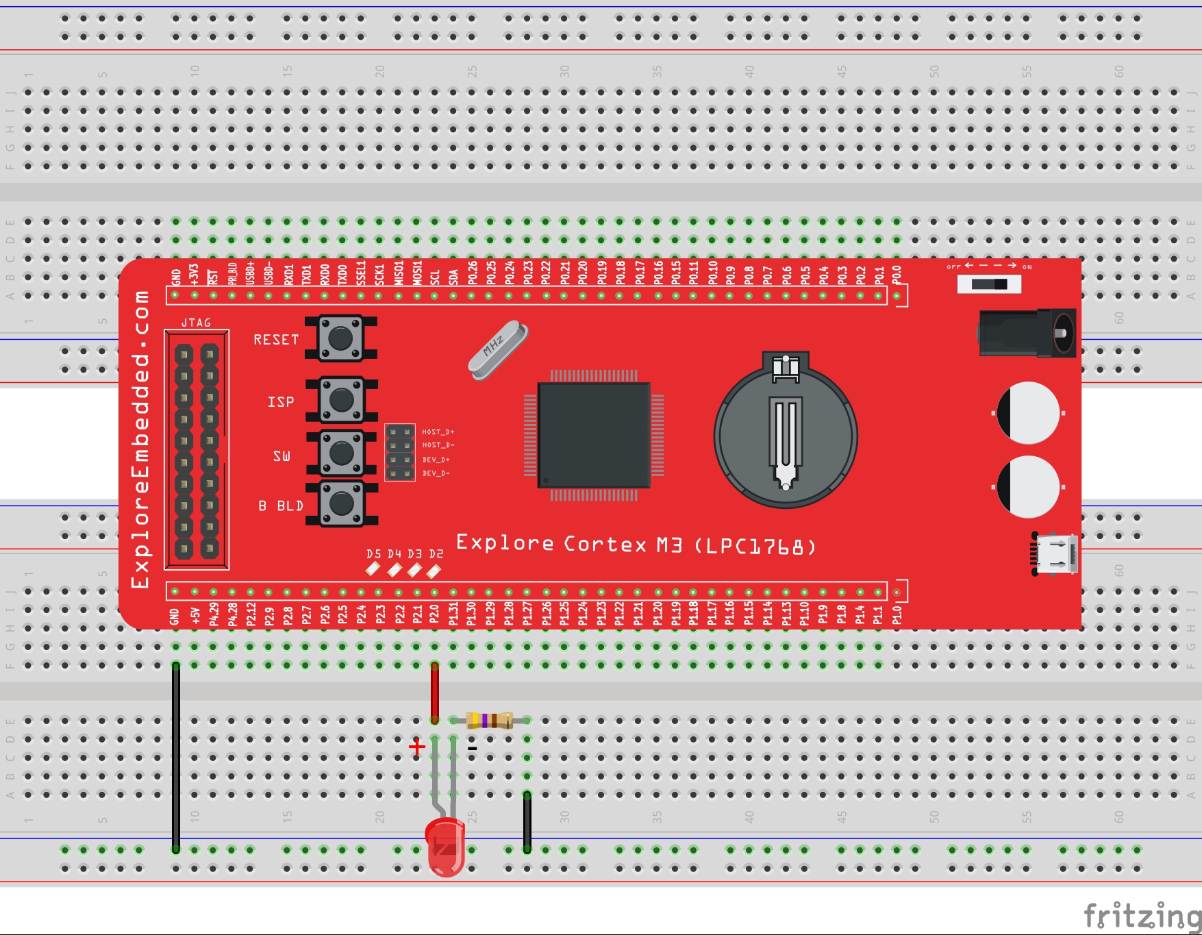
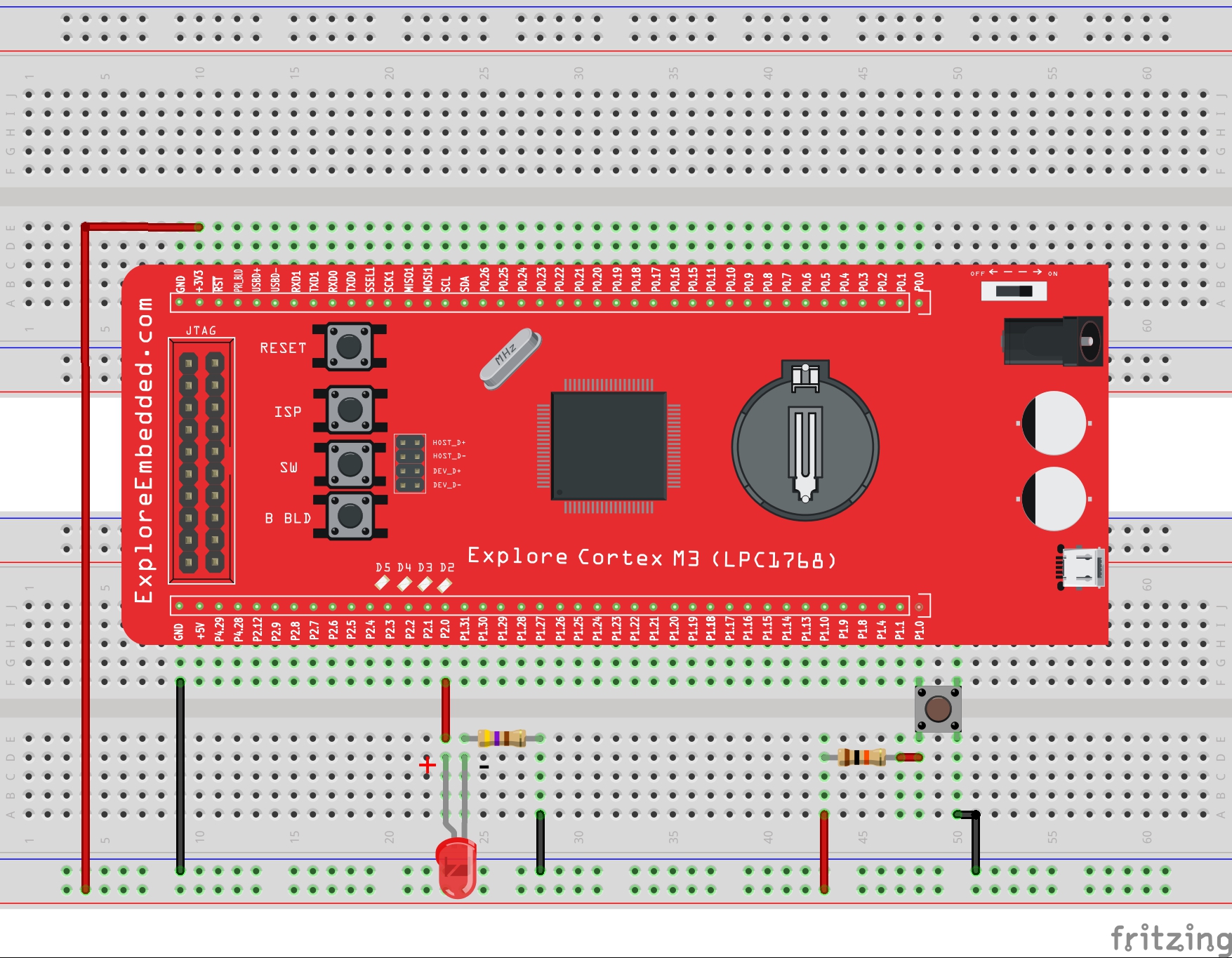
Hardware Connections

Schematic
Examples
Example 1
In this program we are going to do both INPUT and OUTPUT operation. The port pin to which switch is connected is configured as Input and the pin to which LED is connected is configured as OUTPUT. Here the switch status is read and accordingly the LED will be turned ON/OFF.
| #include <lpc17xx.h> | |
| #define SwitchPinNumber 11 | |
| #define LedPinNumber 0 | |
| /* start the main program */ | |
| void main() | |
| { | |
| uint32_t switchStatus; | |
| SystemInit(); //Clock and PLL configuration | |
| LPC_PINCON->PINSEL2 = 0x000000; //Configure the Pins for GPIO; | |
| /* Configure the LED pin as output and SwitchPin as input */. | |
| LPC_GPIO2->FIODIR = ((1<<LedPinNumber) | (0<<SwitchPinNumber)); | |
| while(1) | |
| { | |
| /* Turn On all the leds and wait for one second */ | |
| switchStatus = (LPC_GPIO2->FIOPIN>>SwitchPinNumber) & 0x01 ; // Read the switch status | |
| if(switchStatus == 1) //Turn ON/OFF LEDs depending on switch status | |
| { | |
| LPC_GPIO2->FIOPIN = (1<<LedPinNumber); | |
| } | |
| else | |
| { | |
| LPC_GPIO2->FIOPIN = (0<<LedPinNumber); | |
| } | |
| } | |
| } |
Example 2
This is the alternate method using the stdutils macros.
| #include <lpc17xx.h> | |
| #include "delay.h" //User defined library which contains the delay routines | |
| #include "stdutils.h" | |
| #define SwitchPinNumber 11 | |
| #define LedPinNumber 0 | |
| /* start the main program */ | |
| void main() | |
| { | |
| uint32_t switchStatus; | |
| SystemInit(); //Clock and PLL configuration | |
| LPC_PINCON->PINSEL2 = 0x000000; //Configure the Pins for GPIO; | |
| /* Configure the LED pin as output and SwitchPin as input */. | |
| LPC_GPIO2->FIODIR = ((1<<LedPinNumber) | (0<<SwitchPinNumber)); | |
| while(1) | |
| { | |
| /* Read the switch status */ | |
| switchStatus = util_GetBitStatus(LPC_GPIO2->FIOPIN,SwitchPinNumber); | |
| if(switchStatus == 1) //Turn ON/OFF LEDs depending on switch status | |
| { | |
| util_BitSet(LPC_GPIO2->FIOPIN,LedPinNumber); | |
| } | |
| else | |
| { | |
| util_BitClear(LPC_GPIO2->FIOPIN,LedPinNumber); | |
| } | |
| } | |
| } |
Example 3
In this program multiple(3) switches are read and multiple LEDs are turned ON/OFF depending on the respective switch status. As shown in the schematic the LEDs are connected from P2.0 to P2.3. And the switches are connected to P2.10 to P2.12, accordingly the 3bit mask will be 0x07.
| #include <lpc17xx.h> | |
| #define SwitchPinNumber 10 | |
| #define LedPinNumber 0 | |
| #define ThreeBitMask 0x07 | |
| /* start the main program */ | |
| void main() | |
| { | |
| uint32_t switchStatus; | |
| SystemInit(); //Clock and PLL configuration | |
| LPC_PINCON->PINSEL2 = 0x000000; //Configure the Pins for GPIO; | |
| /* Configure all the LED pins as output and SwitchPins as input */ | |
| LPC_GPIO2->FIODIR = ((ThreeBitMask<<LedPinNumber) | (0<<SwitchPinNumber)); | |
| while(1) | |
| { | |
| /* Read the switch status*/ | |
| switchStatus = (LPC_GPIO2->FIOPIN>>SwitchPinNumber) & ThreeBitMask ; | |
| LPC_GPIO2->FIOPIN = (switchStatus<<LedPinNumber); //Turn ON/OFF LEDs depending on switch status | |
| } | |
| } |
Using Explore Embedded Libraries :
In the above tutorial we just discussed how to configure the PORTS for GPIO and use them for reading/wring the pins
Once you know the GPIO configurations, you can directly use the ExploreEmbedded libraries
For that you need to include the gpio.c/gpio.h and the associated files(delay/stdutils).
The below sample code shows how to use the GPIO functions.
Refer this link for more info on GPIO libraries.
| #include <lpc17xx.h> | |
| #include "delay.h" //User defined library which conatins the delay routines | |
| #include "gpio.h" | |
| #define MY_LED P2_0 // Led is connected to P2.0 | |
| #define MY_SWITCH P2_10 // Switch is connected to P2.10 | |
| /* start the main program */ | |
| void main() | |
| { | |
| uint8_t value; | |
| SystemInit(); //Clock and PLL configuration | |
| GPIO_PinFunction(MY_SWITCH,PINSEL_FUNC_0); // Configure Pin for Gpio | |
| GPIO_PinDirection(MY_SWITCH,INPUT); // Configure the switch pin as Input | |
| GPIO_PinFunction(MY_LED,PINSEL_FUNC_0); // Configure Pin for Gpio | |
| GPIO_PinDirection(MY_LED,OUTPUT); // Configure the Led pin as OUTPUT | |
| while(1) | |
| { | |
| value = GPIO_PinRead(MY_SWITCH); // Read the switch status | |
| GPIO_PinWrite(MY_LED,value); // ON/OFF the led as per switch status | |
| } | |
| } |
Downloads
Download the complete project folder from the below link:
https://codeload.github.com/ExploreEmbedded/Explore-Cortex-M3-LPC1768-Stick-DVB-14001/zip/master
{{#widget:Facebook_Like_Box|profile=https://www.facebook.com/ExploreEmbedded}}
Have a opinion, suggestion , question or feedback about the article let it out here!
LPC1768: Led Blinking
This is first example on LPC1768 where we start with blinking the LEDs. In this tutorial, we are going to discuss how to configure the LPC1768 ports as GPIO and then send a low/high signal...
LPC1768: Switch and LED
This is second tutorial on LPC1768 where we are going to read the switches and turn ON/OFF the LEDs accordingly. LPC1768 has its GPIOs divided into five ports PORT0 - PORT4, although many of them...
LPC1768: Lcd 4bit
In this tutorial we are going to see how to interface a 2x16 LCD with LPC1768 in 4-bit mode. As per the name the 2x16 has 2 lines with 16 chars on each lines. It supports all the ascii chars and is...

LPC1768: Lcd 8bit
In this tutorial we are going to see how to interface a 2x16 LCD with LPC1768 in 8-bit mode. As per the name the 2x16 has 2 lines with 16 chars on each lines. It supports all the ascii chars and is...