
Difference between revisions of "Interfacing RTC with AVR Breakout"
| Line 17: | Line 17: | ||
<br/> | <br/> | ||
[[file:00Interface RTC with Atmega128.gif]] | [[file:00Interface RTC with Atmega128.gif]] | ||
| + | =Downloads= | ||
| + | Download the complete project folder from the below link: | ||
| + | https://github.com/ExploreEmbedded/AVR-MCU-Breakout-Board/archive/master.zip<br> | ||
| + | |||
| + | |||
| + | |||
| + | Have a opinion, suggestion , question or feedback about the article let it out here! | ||
| + | {{DISQUS}} | ||
Latest revision as of 10:17, 20 April 2016
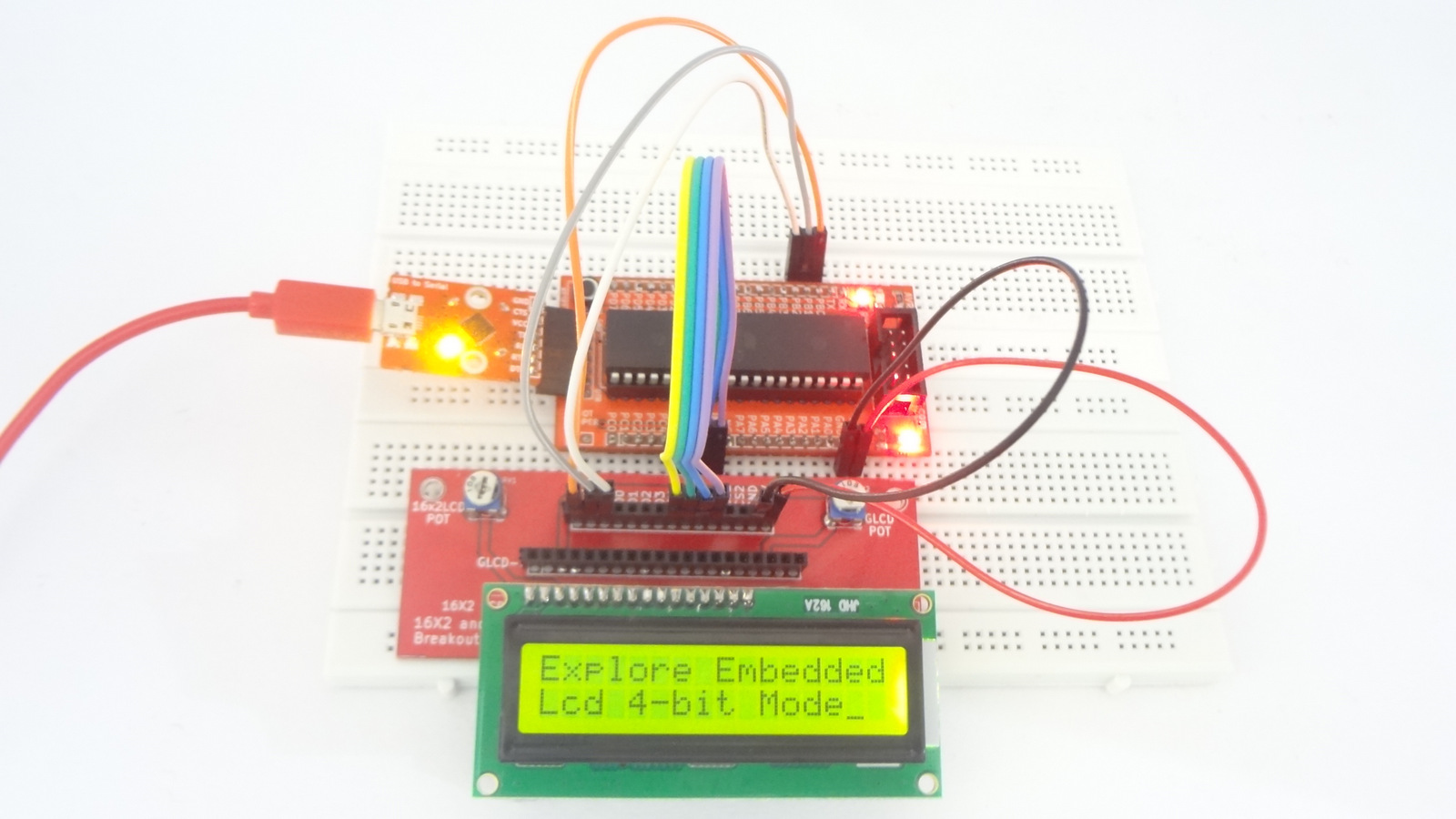
Now in this tutorial we will interface RTC (Real time clock) with Atmega32 breakout board. For this tutorial we will require RTC Breakout ,LCD Breakout and 16x2 LCD to display the time.
Contents
[hide]Basics
In this example we are using DS1307 RTC. It will communicate through I2C protocol with controller. Connect SCL and SDA of RTC Breakout to SCL and SDA of ATmega32. Connect D4 to D7 of LCD Breakout to PORT B4 to PORT B7
and RS,R/W,E to PORT B0 to PORT B2 respectively as shown in hook up.
Refer Real Time Clock(DS1307) with AVR tutorial for RTC basics.
Hook Up

Code
| #include "rtc.h" | |
| #include "lcd.h" | |
| int main() | |
| { | |
| rtc_t rtc; | |
| /*Connect RS->PB0, RW->PB1, EN->PB2 and data bus to PORTB.4 to PORTB.7*/ | |
| LCD_SetUp(PB_0,PB_1,PB_2,P_NC,P_NC,P_NC,P_NC,PB_4,PB_5,PB_6,PB_7); | |
| LCD_Init(2,16); | |
| /*Connect SCL->PC0, SDA->PC1*/ | |
| RTC_Init(); | |
| rtc.hour = 0x10; // 10:40:20 am | |
| rtc.min = 0x40; | |
| rtc.sec = 0x00; | |
| rtc.date = 0x01; //1st Jan 2016 | |
| rtc.month = 0x01; | |
| rtc.year = 0x16; | |
| rtc.weekDay = 5; // Friday: 5th day of week considering monday as first day. | |
| /*##### Set the time and Date only once. Once the Time and Date is set, comment these lines | |
| and reflash the code. Else the time will be set every time the controller is reset*/ | |
| RTC_SetDateTime(&rtc); // 10:40:20 am, 1st Jan 2016 | |
| /* Display the Time and Date continuously */ | |
| while(1) | |
| { | |
| RTC_GetDateTime(&rtc); | |
| LCD_GoToLine(0); | |
| LCD_Printf("time:%2x:%2x:%2x \nDate:%2x/%2x/%2x",(uint16_t)rtc.hour,(uint16_t)rtc.min,(uint16_t)rtc.sec,(uint16_t)rtc.date,(uint16_t)rtc.month,(uint16_t)rtc.year); | |
| } | |
| return (0); | |
| } |

Downloads
Download the complete project folder from the below link:
https://github.com/ExploreEmbedded/AVR-MCU-Breakout-Board/archive/master.zip
Have a opinion, suggestion , question or feedback about the article let it out here!
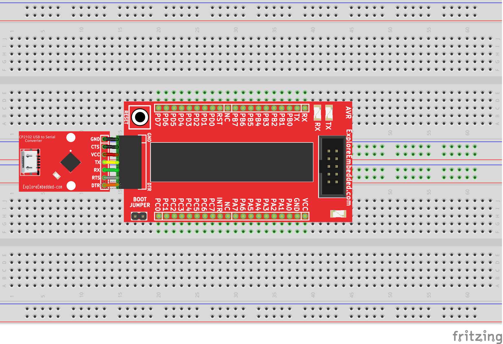
Setting Up AVR Breakout
In this tutorial we will look at the basic setup required to get started with AVR breakout board. After completion of this basic setup we can interface peripherals with the breakout board. ...
Blinky with AVR Breakout
In this tutorial we will get hands on with AVR breakout board. Here we will interface simple LED with one of the port pins. For this tutorial we will require a breadboard, LEDs and resistors. ...
Interfacing LCDs with AVR Breakout
In this tutorial let's interface a 16x1,16x2 and 20x4 character display with AVR breakout board. For this tutorial we will require a LCD Breakout. Basics LCD can be interfaced with...
Interfacing Seven Segment Display with AVR Breakout
After blinking the LED , Let's display user information like numeric value using seven segment display. In this tutorial we will interface a seven segment display to AVR breakout board and display a...