2 -Read Switch and Display on LED
Read Switch and Display on LED
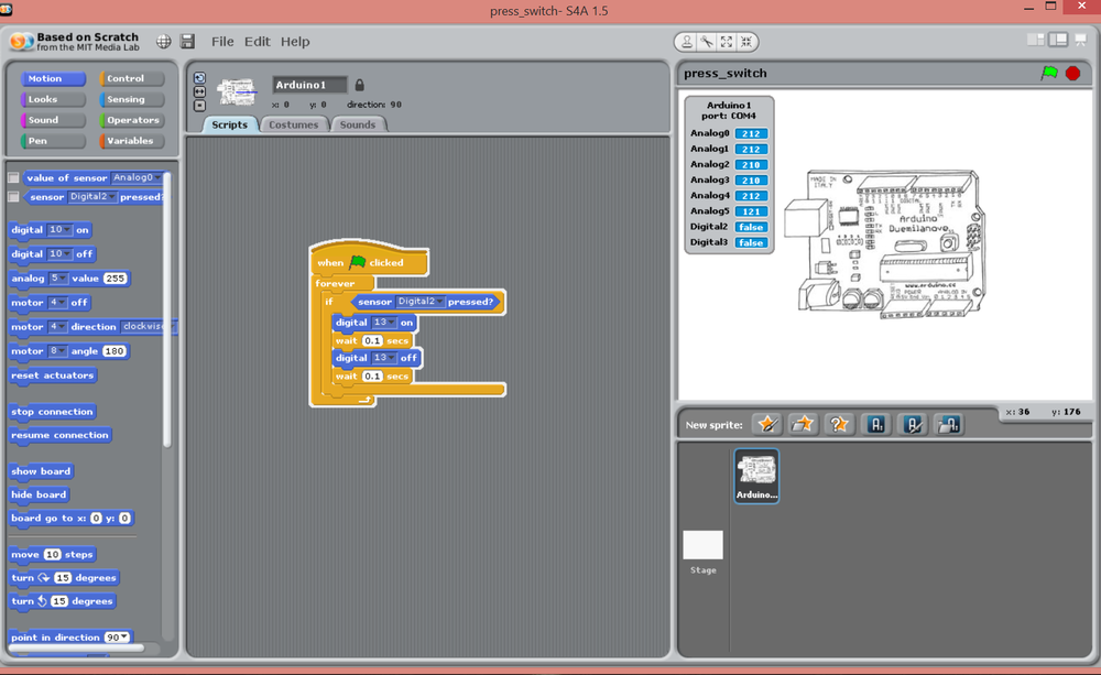
digital 2 is declared as the input port to read the values from the switch.
digital 13 is the output LED for our board in this experiment
wait 0.1 is the delay timing
Our experiment can be resume as :
when Button is clicked forever  when (if)  digital 2  send the value 1 to the digital 13 ,it receive it and on the LED for 0.1 sec then off when it is released hence digital 13 receive 0 for 0.1 sec
and its will keep repeating until stop is clicked


