
Explore POV
Sandeep (talk) 15:35, 6 March 2015 (IST)
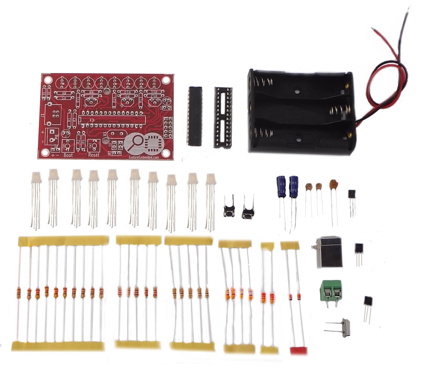
The colorful Persistence Of Vision (POV) kit enables you to create colorful messages in air with just 8 LEDs. This kit is great introduction to soldering and AVR/Arduino Programming. The kit does not require a external programmer, it is self programmable with USB.


DIY Kit contains

Component Placement


Contents
[hide]Solder it!

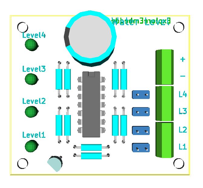
- Image above shows the layout of various components for the board. It is also printed on the PCB.
- The image sequence shows, how to mount and solder components!
Component Layout
The image shows reference numbers for all the components.
- From the table below find out the exact part for the reference number.
Component List
|
|
|
|
|---|---|---|
|
|
|
|
|
|
|
|
|
|
|
|
|
|
|
|
|
|
|
|
|
|
|
|
|
|
|
|
|
|
|
|
|
|
|
|
|
|
|
|
|
|
|
|
|
|
|
|
|
|
|
|
|
|
|
|
|
|
|
|
|
|
|
|
|
|
|
|
|
|
|
|
Programming
C Code
- #include <avr/io.h>
- #include<util/delay.h>
- #include<stdint.h>
- #include<avr/interrupt.h>
- #define Blue 3
- #define Green 4
- #define Red 5
- uint8_t i=0;
- const static uint16_t image[]=
- {
- 0b0000100011111111, 0b0000100011111111, 0b0000100011111111, 0b0000100011111111,
- 0b0000100011111111, 0b0000100011111111, 0b0000100011111111, 0b0000000000000000,
- 0b0000010011111110, 0b0000010000010001, 0b0000010000010001, 0b0000010000010001,
- 0b0000010011100001, 0b0000000000000000, 0b0000010001111110, 0b0000010010010001,
- 0b0000010010010001, 0b0000010010010001, 0b0000010000001110, 0b0000000000000000,
- 0b0000001011111111, 0b0000001000010001, 0b0000001000010001, 0b0000001000010001,
- 0b0000001000001110, 0b0000000000000000, 0b0000001000001110, 0b0000001000010001,
- 0b0000001000010001, 0b0000001011111111, 0b0000000000000000, 0b0000000000000000,
- 0b0000100001110000, 0b0000100011111100, 0b0000100011111110, 0b0000100011111111,
- 0b0000100011111111, 0b0000100011111110, 0b0000100011111100, 0b0000100001111000,
- 0b0000000000000000, 0b0000000000000000, 0b0000010011111110, 0b0000010000010001,
- 0b0000010000010001, 0b0000010000010001, 0b0000010011100001, 0b0000000000000000,
- 0b0000001001110000, 0b0000001010001000, 0b0000001010001000, 0b0000001010001000,
- 0b0000001011111111, 0b0000000000000000, 0b0000001001110000, 0b0000001010001000,
- 0b0000001010001000, 0b0000001010001000, 0b0000001011111111, 0b0000000000000000,
- 0b0000010001111110, 0b0000010010010001, 0b0000010010010001, 0b0000010010010001,
- 0b0000010010001111, 0b0000000000000000, 0b0000000000000000, 0b0000010011111111,
- 0b0000010000010000, 0b0000010000010000, 0b0000010000010000, 0b0000010011111111
- };
- void disp(uint16_t);
- ISR (TIMER1_OVF_vect) // Timer1 ISR
- {
- disp(image[i]);
- i++;
- if(i==72)
- i=0;
- TCNT1H=0xFF; // Reload the 16-bit count value
- TCNT1L=0xF0; // in timer1 count registers
- }
- int main(void)
- {
- DDRC = 0b11111111;
- DDRD = 0b11111111;
- PORTC = 0b11111111;
- PORTD = 0b00000111;
- TCNT1H=0xFF; // Load the 16-bit count value
- TCNT1L=0xF0; // for 1 sec at 7.3728MHz
- TCCR1A=0x00;
- TCCR1B=0x05; // Timer mode with 1024 prescAler
- TIMSK=0x04; // Enable timer1 overflow interrupt(TOIE1)
- sei(); // Enable global interrupts by setting global interrupt enable bit in SREG
- while(1)
- {
- }
- }
- void disp(uint16_t pat)
- {
- PORTC = pat & 0x3f;
- PORTD = (pat>>6)& 0xff;
- }
Arduino Code
Arduino Code will be uploaded soon.
Pattern Generation
To create an image/patterm, you can use the POV image maker application.

Uploading the Pattern
- Install USBasp driver on your computer. Note that the it will show up as not recognized if the reset sequence is not followed
Reset Sequence for uploading new pattern/image

- Perform reset sequence every time you connect the kit to the computer.
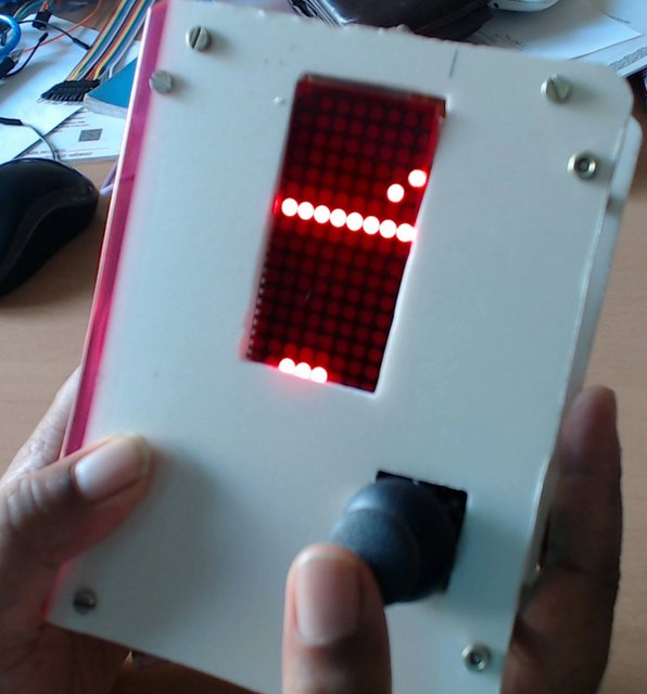
- To upload a new image, hold down the BOOT button, press and release the RESET button and then release the BOOT button as shown below.
- Note the LEDS will stop blinking once the kit is detected by the computer.
Downloads
Explore POV
Sandeep (talk) 15:35, 6 March 2015 (IST) The colorful Persistence Of Vision (POV) kit enables you to create colorful messages in air with just 8 LEDs. This kit is great introduction to soldering...
Water Level Indicator
By : Sandeep 11:49, 6 March 2015 (IST) At times you just need a simple device that just works and this is one. This DIY kit indicates the level of water and sets an buzzer whenever...
Explore Ping-Pong with Arduino
Retro gaming is nostalgia, isn't it? We will look at building the simplest Ping pong game with LED Matrix Display and a Joystick using Arduino. The setup can be used to program and play other retro...

Building a LED matrixGame console with Arduino
Retro games are cool! The pixel games like tetris, ping-pong, snake etc., are fun to play with physical buttons instead of a touch screen. In this tutorial, we will build a Retro gaming console...