
Interfacing Seven Segment Display with Starter AVR
Now we will go further and will interface more complex peripherals. In this tutorial we will interface common anode 7 segment display to the starter AVR board. To get idea about basics of 7 segment display check out our Interfacing Seven Segment Displays with AVR tutorial.
Basic
In this example we are using common anode type of 7 segment display. To give positive voltage to the common anode I am using BC547, N-Type transistor as a driver and PD0 is used to drive this driver. PD0 is connected to the base of transistor through 68 Ohm resistor and VCC is given to collector through 1K resistor. Emitter of transistor is given to common pin of 7 segment display. Data lines of display is connected to PORTB. Do the connection as shown in hookup and flash the code.
Hookup

Code
| #include <avr/io.h> | |
| #include <util/delay.h> | |
| #define Segment 0x01 | |
| int main() { | |
| char seg_code[]={0xc0,0xf9,0xa4,0xb0,0x99,0x92,0x82,0xf8,0x80,0x90,0x88,0x83,0xc6,0xa1,0x86,0x8e}; | |
| int cnt; | |
| /* Configure the ports as output */ | |
| DDRB = 0xff; // Data lines | |
| DDRD = 0x01; // Control signal PORTD0 | |
| while (1) | |
| { | |
| for (cnt = 0x00; cnt < 0x10; cnt++) // loop to display 0-F | |
| { | |
| PORTD = Segment; | |
| PORTB = seg_code[cnt]; | |
| _delay_ms(300); | |
| } | |
| } | |
| } |
Demo

Downloads
Download the complete project folder from the below link:
https://github.com/ExploreEmbedded/ATmega32_ExploreStarterAvr/archive/master.zip
Have a opinion, suggestion , question or feedback about the article let it out here!
Setting Up Starter AVR
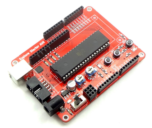
In this tutorial we will look at setting up the starter AVR board. Once you have done with this basic set up, you can use on board peripherals as well as many other peripherals which can be connected...
Blinky with Starter AVR
After setting up starter AVR board, we will start with simple LED blinking experiment. Two user LED's are provided on starter AVR board, we will use same for this experiment. Basic ...
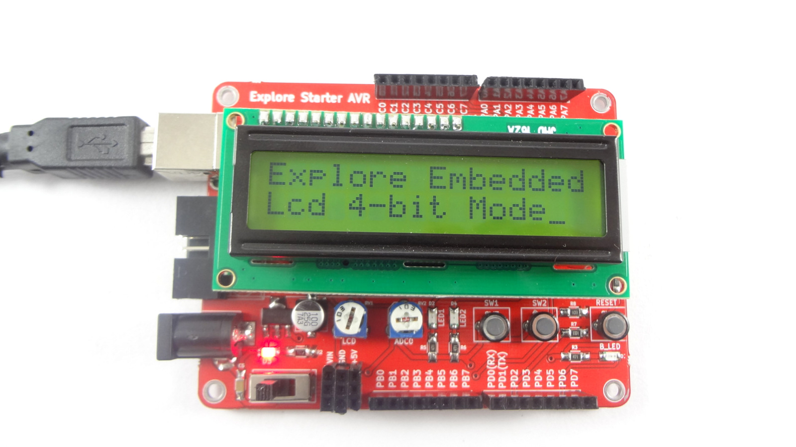
Interfacing LCD with Starter AVR
In this tutorial we'll look at how to interface different types of character LCD's to the starter AVR board. Basic Starter AVR board has female connector on board to connect LCD's...
Interfacing Seven Segment Display with Starter AVR
Now we will go further and will interface more complex peripherals. In this tutorial we will interface common anode 7 segment display to the starter AVR board. To get idea about basics of 7 segment...